1.Introduction of Zencrack
Zencrack is a state-of-the-art software tool for 3D fracture mechanics simulation. It is developed by Zentech(set up in 1980)which is specialized in engineering consultancy and advanced software solutions. Zencrack uses finite element analysis to allow calculation of fracture mechanics parameters such as energy release rate and stress intensity factors. This is achieved by automatic generation of focused cracked meshes from uncracked finite element models. In addition, a crack growth methodology is included that provided non-planar crack growth prediction for fatigue and time-dependent load conditions via automated adaptive meshing techniques.
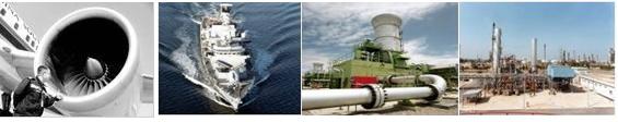
Zencrack can be applied in any industry with crack behaviour, crack growth prediction and residual life calculation, e.g: Aerospace, Nuclear, Manufacturing, Offshore, Power generation. And it can be using in:
- Assessing residual life, life extension, damage tolerance assessment;
- Reliability analysis
- Development of new material
- Engine disks and blades and their dovetail connections
- Power generation components, e.g High pressure waterbox
- Pipeline defects and connections
- Rubber components
- High temperature creep Ct integral evaluation
- Rail track
2.Features of Zencrack
Zencrack is available in two versions – Standard and Professional. And crack growth capability is only available in Zencrack professional. Zencrack can utilize the commercial f.e coding to calculate fracture parameters. Now the general reference is made to the Abaqus, ANSYS, Finas & MSC.Marc
The Zencrack Standard version is ideal for parametric studies of different crack sizes and calculation of stress intensity factors, G and J for those cracks.
The Zencrack Professional version provide all of the capabilities of the Standard version for analysis of one-off crack size plus the options to analysis fatigue, time dependent or combined fatigue and time dependent crack growth. These crack growth options cater for non-planar growth and incorporate methods for allowing defects to grow through a mesh
2.1 Zencrack working Process
Firstly, user must supply zencrack with a mesh that must contain 8 or 20 node brick elements in the region where crack is required.
Secondly, user must supply a supplementary data which contain specification of the required location, orientation and size of the initial crack front. For crack growth prediction additional data such as the crack growth law data is required.
Zencrack will generate a mesh with initial mesh. In this mesh, boundary conditions and pressure loads are updated near the crack front. J-integral and/or COD requests are generated for the new mesh.
Then the cracked component mesh is automatically submitted for analysis using f.e coding. This is the last step if the user only wants to evaluate stress intensities or the energy release rate for a given crack size.

If user wants a crack growth prediction with a professional version, Zencrack extracts the required information from the analysis output and calculates a new crack front position and the mesh is updated to contain a crack in this new position.

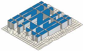
2.2 Crack - Block Approach in Zencrack
Zencrack uses a ‘crack-block’ approach to introduce crack fronts into a mesh. A crack-block is a mesh of brick elements which models a section of a crack front. Crack-blocks are mapped into an intact mesh replacing standard brick elements (8 or 20 nodes) in the intact mesh. User can use one or more of these crack-blocks to defined size and position of crack.

2.3 Load system
Zencrack supply two superposition methods are available to allow combination of different load types into a load spectrum, these two methods are refer to cyclic-static and max-min.
The cyclic-static method assumes that all steps in the finite element analysis are linear elastic and that results from individual steps can be scaled and combined.
The max-min method is intended for us when the superposition of loading is carried out in the finite element load steps. This is most likely to occur when non-linearities are introduced in the finite element analysis such as plasticity or crack face contact.

2.4 Boundary shift and relax
Boundary shift can be used when there is no crack growth to enable shifting of element boundaries in a model. this can allow modeling of an otherwise awkward crack size. In addition, crack fronts consisting of only through crack-blocks can be made to transfer from one set of element locations to another as crack grows and this also need relaxing algorithm, this can improve the mesh around the crack-block region.

2.5 Pre/Post Processing
There are two tools in zencrack pre processing.
One is utility “TANH”. It can produces tabular crack
Growth data from tanh equation data. The other is utility program “rainflow”, it can help user to cycle counting of uncounted load spectra and the output is spectrum file ready for use by Zencrack.

TANH Rainflow
Process can creates a comma delimited (.csv) file from the output data in the .rep file and can be imported into a spread sheet. “3DMESH” is used produce beam element meshes representing crack growth.

Process 3DMESH
3.Zencrack benefits
Zencrack can be used to predict 3-D cracks behavior under static loading and their growth under both fatigue and time-dependent loading, by using Zencrack, you can
- Increase the efficiency and productivity of your 3D fracture mechanics workforce
- Reduce your pre and post-processing time for 3D finite element crack analysis
- Analyze problems that cannot be tackled using conventional fracture mechanics methods
- Use of industry-standard finite element software as part of the overall solution
- Complex non-planar crack shapes and geometries can be analysed
- A wide range of complex loading can be applied, including: Residual stress from shot peening, spectrum load files.
4. Customers
Zencrack has a vast user groups, ranging from engineering consultants to R&D labs and blue-chip companies, government defense research bodies and various academic institution.
- Aeronautical and Maritime Research Laboratory
- Materials Center Leoben
- CENAERO
- COPPE/UFRJ
- National Research Council Canada
- Ning Xia Yi Fei Institute
- Huazhong University of Science and Technology
- Hefei Institute of General Professional Tech
- Xi'an Aircraft Company
- The First Machine Manufacturing Corp
- Chengdu Aircraft R&D Institute
- Shanghai Maritime University
- Tongji University
- Tsinghua University
- Shenyang Aircraft R&D Institute
- VTT
- PSA Peugeot Citroën
- Univ Technol Troyes
- Robert Bosch GmbH
- Rolls-Royce Deutschland Ltd & Co KG
- Siemens AG
- Technische Universität Chemnitz
- Robert Bosch GmbH
- GTRE
- Government College of Engineering
- Indian Institute of Technology Hyderabad
- Defense Materials Research Labs
- National Aeronautical Labs
- Dept Of Aerospace Engg
- Faculty of Mech. Eng.
- Politecnico di Milano
- Hitachi Ltd.
- Ibaraki University
- Nagoya University
- Kochi University of Technology
- Hosei University
- Tohoku Electric Power Engineering & Construction
- Fukui University
- Sumitomo Metal Industries
- Ecotopia Science Institute
- Shibata Chemical Engineering Co.
- Ishikawajima-Harima Heavy Industries Co.
- Kyoto University Faculty of Engineering
- Osaka University
- Hannam Unversity
- Hankuk Aviation University
- Department of Mechanical and Material Engine
- Instituto Superior Técnico (IST)
- Nanyang Technological University
- Universidad de Sevilla
- Brunel University
- Wolfson School of Mechanical & Manufacturing
- AMEC NNC Ltd.
- University Of Nottingham
- Advantica
- QinetiQ - Scotland
- QinetiQ - Farnborough
- Ecole des Mines de Douai
- Rolls Royce plc
- University of London
- Analysis Design Productivity Limited
- NEWI University of Wales
- Structural Integrity Assessments Limited
- Aberdeen University
- E.ON UK
- Frazer-Nash Consultancy Limited
- Heriot-Watt University
- Massachusetts Institute of Technology
- UNC-Charlotte
- Joshua Hogg
- University of Rochester
- U.S. Geological Survey
- Wichita State University
- CALTECH (Tadashi Iijima)
- Air Force Research Laboratory
- Kx Simulation Technologies Inc
- Rolls-Royce Corporation
- Structural Integrity, Inc.